

Hey there! I'm a supplier of DC - DC Power Converter Modules, and today I'm gonna share with you how to design a custom DC - DC Power Converter Module. It's a pretty cool topic, and I hope by the end of this blog, you'll have a good grasp of the process.
Understanding the Basics
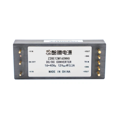
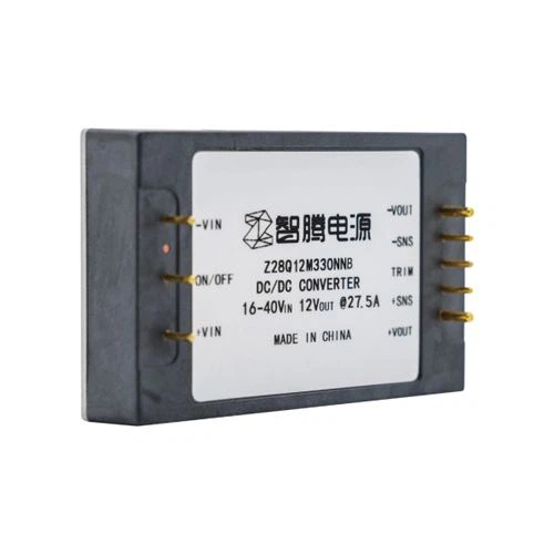
First things first, let's talk about what a DC - DC Power Converter Module is. Simply put, it's a device that converts one DC voltage level to another. This is super useful in a bunch of applications, like in electronic devices where different components need different voltage levels to operate properly. You can learn more about DC - DC Power Converter Module on our website.
The basic principle behind a DC - DC converter is to store energy in an inductor or capacitor and then release it at a different voltage level. There are different types of DC - DC converters, such as buck converters (which step down the voltage), boost converters (which step up the voltage), and buck - boost converters (which can do both).
Defining the Requirements
The very first step in designing a custom DC - DC Power Converter Module is to clearly define your requirements. You need to figure out what input voltage range you'll be dealing with. For example, if you're designing a converter for a battery - powered device, the battery voltage might vary as it discharges. So, you need to know the minimum and maximum input voltage values.
Next, you have to determine the output voltage. This depends on the needs of the load. If you're powering a microcontroller, it might require a specific voltage like 3.3V. You also need to consider the output current. How much current does the load need? This will affect the power rating of the converter.
Another important factor is the efficiency. You want your converter to be as efficient as possible because a less efficient converter will waste energy in the form of heat. High - efficiency converters are also better for battery - powered devices as they can extend the battery life.
Selecting the Topology
Once you've defined your requirements, it's time to select the appropriate topology. As I mentioned earlier, there are buck, boost, and buck - boost converters.
If your output voltage is lower than the input voltage, a buck converter is a good choice. It's relatively simple and efficient for step - down applications. The basic circuit of a buck converter consists of a switch (usually a MOSFET), an inductor, a capacitor, and a diode. When the switch is on, the inductor stores energy, and when the switch is off, the inductor releases the energy to the output.
On the other hand, if you need to step up the voltage, a boost converter is the way to go. A boost converter has a similar circuit to the buck converter, but the operation is different. When the switch is on, the inductor stores energy, and when the switch is off, the inductor voltage adds to the input voltage, resulting in a higher output voltage.
If your application requires the ability to step up or step down the voltage, a buck - boost converter is a suitable option. However, it's a bit more complex than the other two topologies.
Component Selection
After choosing the topology, you need to select the right components. The switch is a crucial component. You want a switch with low on - resistance to minimize power losses. MOSFETs are commonly used as switches in DC - DC converters because they can handle high currents and have fast switching speeds.
The inductor is also important. Its value depends on the switching frequency, input and output voltages, and the output current. A larger inductor value can reduce the ripple current, but it also takes up more space and can be more expensive.
The capacitor is used to filter the output voltage and reduce the ripple. You need to choose a capacitor with the right capacitance and voltage rating. Electrolytic capacitors are often used for high - capacitance applications, but they have a relatively large size and a limited lifespan. Ceramic capacitors are smaller and have a longer lifespan, but they usually have lower capacitance values.
Control and Protection Circuits
To make your DC - DC Power Converter Module work properly, you need to design control and protection circuits. The control circuit is responsible for regulating the output voltage. There are different control methods, such as pulse - width modulation (PWM). In a PWM - controlled converter, the duty cycle of the switch is adjusted to maintain a constant output voltage.
Protection circuits are essential to prevent damage to the converter and the load. Over - current protection is used to limit the output current in case of a short - circuit or a faulty load. Over - voltage protection is used to prevent the output voltage from exceeding a safe value. Under - voltage lockout (UVLO) is used to disable the converter when the input voltage is too low.
PCB Design
Once you've designed the circuit, it's time to design the printed circuit board (PCB). The PCB layout is important because it can affect the performance of the converter. You need to pay attention to the placement of components to minimize the parasitic inductance and capacitance.
Keep the power traces short and wide to reduce the resistance and voltage drop. Separate the power and signal traces to avoid interference. Also, make sure to provide enough ground planes for proper grounding.
Testing and Optimization
After the PCB is fabricated and the components are assembled, it's time to test the converter. You need to measure the input and output voltages, currents, and efficiency. Check for any abnormal behavior, such as overheating or excessive ripple.
If you find any issues, you need to optimize the design. This might involve adjusting the component values, changing the PCB layout, or modifying the control algorithm. You might need to go through several iterations of testing and optimization to get the converter to perform as expected.
Conclusion
Designing a custom DC - DC Power Converter Module is a multi - step process that requires a good understanding of the basic principles, careful component selection, and proper testing and optimization. By following the steps outlined in this blog, you can design a converter that meets your specific requirements.
If you're interested in custom DC - DC Power Converter Modules, we're here to help. We have a team of experienced engineers who can work with you to design the perfect converter for your application. Whether you need a simple buck converter or a complex buck - boost converter, we've got you covered. Contact us to start the procurement and洽谈 process, and let's work together to create a high - quality power converter module.
References
- Erickson, Robert W., and Dragan Maksimovic. Fundamentals of Power Electronics. Springer, 2001.
- Pressman, Abraham I. Switching Power Supply Design. McGraw - Hill, 2009.