

Hey there! As an IMU supplier, I'm super stoked to share with you how to interface an Inertial Measurement Unit (IMU) with a microcontroller. Whether you're a hobbyist tinkering with cool projects or an engineer working on a high - tech application, understanding this process is key. So, let's dive right in!
First off, what the heck is an IMU? An Inertial Measurement Unit IMU is a device that measures and reports a body's specific force, angular rate, and sometimes the magnetic field surrounding the body, using a combination of accelerometers, gyroscopes, and often magnetometers. It's like having a super - sense for your project, allowing it to understand its orientation and movement in space.
The microcontroller, on the other hand, is the brain of your project. It's a small, low - cost computer on a single integrated circuit that can be programmed to perform specific tasks. When you interface an IMU with a microcontroller, you're essentially giving the brain the ability to sense motion and orientation.
Choosing the Right IMU and Microcontroller
The first step in the whole process is picking the right IMU and microcontroller for your project. There are a ton of options out there, and your choice depends on several factors.
For the IMU, you need to consider things like accuracy, sensitivity, and the type of measurement it can provide. Some projects might only need a basic accelerometer and gyroscope combo, while others, like a navigation system, could require the addition of a magnetometer. Also, think about the data output rate. If you're working on a high - speed application, you'll need an IMU that can provide data quickly.
When it comes to selecting a microcontroller, look at its processing power, memory, and the communication interfaces it supports. Popular microcontrollers like the Arduino Uno or the Raspberry Pi are great for beginners because they're easy to work with and have a large community of users for support. But if you're working on a more complex project, you might need something with more oomph, like a PIC or an ARM - based microcontroller.
Understanding Communication Interfaces
Once you've got your IMU and microcontroller sorted, you need to understand how they'll talk to each other. There are a few common communication interfaces used for this purpose:
I2C (Inter - Integrated Circuit)
I2C is a popular choice because it's simple and uses only two wires: a serial data line (SDA) and a serial clock line (SCL). It's a multi - master, multi - slave communication protocol, which means you can have multiple devices connected to the same bus. Most IMUs support I2C, and it's relatively easy to implement in your code.
SPI (Serial Peripheral Interface)
SPI is another option. It's generally faster than I2C, making it a good choice for applications where you need to transfer data quickly. SPI uses four wires: a master - out slave - in (MOSI), a master - in slave - out (MISO), a clock (SCK), and a slave select (SS). It's a full - duplex communication protocol, meaning data can be sent and received at the same time.
UART (Universal Asynchronous Receiver - Transmitter)
UART is a simple, asynchronous communication protocol. It uses two wires: a transmit (TX) and a receive (RX) line. It's not as fast as SPI, but it's easy to implement and is compatible with a wide range of devices.
Wiring the IMU to the Microcontroller
Now that you know which communication interface you're going to use, it's time to wire up the IMU to the microcontroller. This part is pretty straightforward, but you need to be careful with the connections.
For an I2C connection, connect the SDA pin on the IMU to the SDA pin on the microcontroller and the SCL pin on the IMU to the SCL pin on the microcontroller. You'll also need to connect the VCC and GND pins for power. Make sure to use pull - up resistors on the SDA and SCL lines if they're not already built into the IMU or microcontroller.
If you're using SPI, connect the MOSI, MISO, SCK, and SS pins between the IMU and the microcontroller. Again, connect the VCC and GND pins for power.
For a UART connection, connect the TX pin on the IMU to the RX pin on the microcontroller and the RX pin on the IMU to the TX pin on the microcontroller. And of course, don't forget the VCC and GND connections.
Writing the Code
Once the hardware is all set up, it's time to write the code to make the IMU and microcontroller work together. The exact code you'll need depends on the programming language and the libraries available for your microcontroller.
If you're using an Arduino, there are many libraries available for different IMUs. For example, if you're using the MPU6050 IMU, you can use the MPU6050 library. Here's a simple example of how to initialize the MPU6050 and read the accelerometer data using the Arduino IDE:
#include <Wire.h>
#include <MPU6050.h>

MPU6050 mpu;

void setup() {
  Wire.begin();
  Serial.begin(9600);

  while (!mpu.begin(MPU6050_SCALE_2000DPS, MPU6050_RANGE_2G)) {
    Serial.println("MPU6050 connection failed!");
    delay(1000);
  }
}

void loop() {
  Vector rawAccel = mpu.readRawAccel();
  Serial.print("Accel X: ");
  Serial.print(rawAccel.XAxis);
  Serial.print(" Y: ");
  Serial.print(rawAccel.YAxis);
  Serial.print(" Z: ");
  Serial.println(rawAccel.ZAxis);

  delay(100);
}
This code initializes the MPU6050, checks if the connection is successful, and then continuously reads and prints the raw accelerometer data.
If you're using a more advanced microcontroller like a PIC or an ARM - based device, you'll need to use a different programming environment, like MPLAB for PIC or Keil for ARM. The process is a bit more involved, but the basic principles are the same.
Calibration
Calibrating the IMU is an important step to ensure accurate measurements. IMUs can have biases and errors due to manufacturing variations and environmental factors. Calibration involves compensating for these errors.
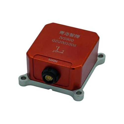
There are different calibration methods depending on the type of IMU. For accelerometers, you can perform a zero - g calibration by placing the IMU on a flat surface and measuring the output. For gyroscopes, you can perform a zero - rate calibration by keeping the IMU still and measuring the output.
Some IMUs have built - in calibration algorithms, while others require you to implement the calibration code in your microcontroller. Calibration can be a bit tricky, but it's worth the effort to get accurate data.
Troubleshooting
If things aren't working as expected, don't panic! Here are some common issues and how to fix them:
- No data received: Check your wiring to make sure all the connections are correct. Also, make sure the power supply is stable. If you're using an I2C or SPI connection, check the pull - up resistors.
- Inaccurate data: This could be due to a calibration issue. Try recalibrating the IMU. It could also be caused by electromagnetic interference. Make sure the IMU is properly shielded.
- Communication errors: If you're getting communication errors, check the communication settings in your code, such as the baud rate for UART or the clock speed for I2C and SPI.
Conclusion and Call to Action
Interfacing an IMU with a microcontroller might seem daunting at first, but with the right knowledge and a bit of patience, you can do it. Whether you're building a robot, a drone, or a fitness tracker, an IMU can add a whole new dimension to your project.
As an IMU supplier, I've got a wide range of high - quality IMUs that can meet your needs. If you're interested in purchasing IMUs for your projects or have any questions about interfacing them with a microcontroller, don't hesitate to reach out. We can have a chat about your specific requirements and find the best solution for you. Let's take your projects to the next level together!
References
- Arduino Documentation
- IMU Datasheets
- Microcontroller User Manuals